6. IEC exclusion areas
IEC exclusion areas are represented by the gray areas in the figure below. The white areas show valid turbine positions. IEC exclusion areas can be calculated as a combination of type and sectors. If only one sector and one constraint type is involved, a map of absolute values can be displayed; otherwise the constraints and sectors are superimposed as logical maps.
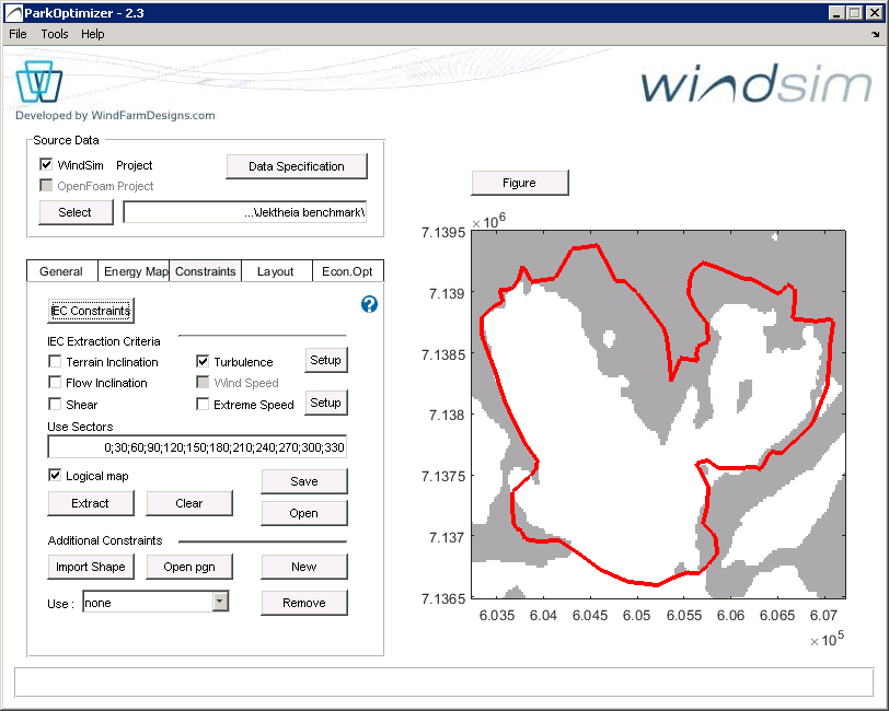
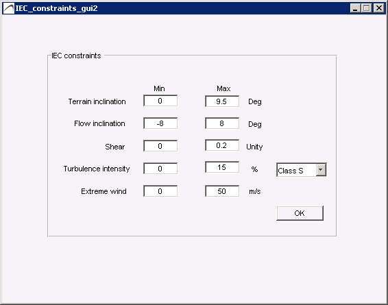
Press the IEC Constraints button to view/edit the constraint limits, and press Extract after selecting one or several IEC Constraints to generate the Constraints Map. By IEC constraints and exclusion areas we refer to the IEC 61400-1 3rd ed. standard (2005) plus its amendment (2010). The constraints considered in ParkOptimizer are terrain inclination, flow inclination, shear, turbulence intensity and extreme wind.
6.1 Terrain inclination
Terrain inclination is not part of the IEC standard but is useful in practice — areas unsuitable for turbine placement because of steep slopes and/or steep road access. These constraints are not absolute and can be remediated by civil works at increased cost. Steep terrain also causes flow inclinations, so these constraints often overlap. Terrain inclination is derived from the WindSim input file \dtm\view_inclination.scl.
6.2 Flow inclination
Flow inclination uses vertical and horizontal wind speeds from the Input files. It is calculated as the maximum inclination over the sectors s at each location (x,y). If the maximum inclination exceeds the constraints defined in IEC constraints definitions, the location is an exclusion and presented as a gray point on the exclusion map.
6.3 Shear
The shear calculation uses wind speed Input Files at heights defined with the Height Definition button. The Wind Resource file provides the sector frequencies f(s). With v₁, v₂, v₃ the wind speeds at heights h₁ = Simulation Height + Shear Deviation, h₂ = Simulation Height, h₃ = Simulation Height − Shear Deviation, the shear coefficient α(s) per sector is the least-squares solution of:
v₁(s)/v₂(s) = (h₁/h₂)^α(s) and v₃(s)/v₂(s) = (h₃/h₂)^α(s)
The shear coefficient α is the sum over the Use Sectors of α(s)·f(s). If the Wind Resource file is not defined, α is set to the maximum over sectors of α(s).
6.4 Turbulence
Turbulence is calculated from the turbulence intensity files at the Simulation Height, scaled according to a tws measurement file (if defined). The Wind Resource file provides the sector frequency distribution. The exclusion areas are computed as the Ambient effective turbulence intensity:
Iₐ/V_hub = (1/V_hub) · [ Σₛ σ_c(s,V_hub)^m · f(s) ]^(1/m)
where m is the Wöhler exponent (default 10 for composite blades, 5 for steel tower), σ_c the characteristic turbulence (σ_c = 1.28·σ_σ, the 90th percentile of the turbulence standard deviation), and V_hub the wind speed at hub height.
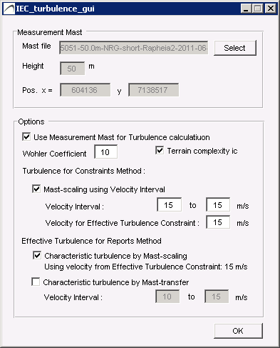
Method 1 — the WindSim turbulence intensity map is used directly (uncheck "Use Measurement Mast"). Recommended when no mast data is available. Method 2 — the WindSim map is scaled with mast data: TI_scaled(s) = TI(s)·f(s)·TI_meas(s)/TI_ws(s), summed over the Use Sectors. The factor ic is a 15% correction in complex terrain per IEC 61400-1.
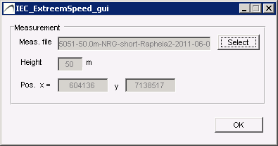
6.5 Extreme wind
Extreme wind estimation uses the method of Independent Storms. The extreme-wind value is obtained from a measurement tws file and scaled within the park according to WindSim wind speeds and directions at the Simulation Height. The tws file should contain 10-minute averages over a duration of at least 3 years.
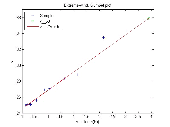
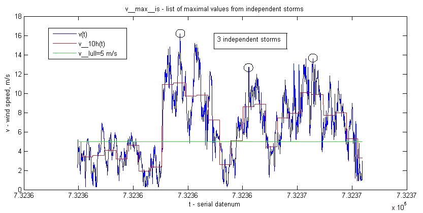
The v₅₀ value is the 10-minute average wind speed reached on average once every 50 years. A list of maxima from independent storms v_max,is is extracted (an independent storm is where the 10-hour averaged wind stays above v_lull = 5 m/s), and a subset v_max of the highest values is fitted to a Gumbel distribution F(v) = exp(−exp(−(v−b)/a)) by weighted least squares, giving:
v₅₀ = [ −ln(−ln(0.98)) ]·a + b
Extreme wind at other locations is estimated by scaling each tws measurement entry by the ratio of WindSim wind speeds f(x,y,s) = v_ws(x,y,s)/v_ws(x_tws,y_tws,s) for the corresponding direction, then performing the v₅₀ estimation on the adjusted values.
6.6 Other constraints
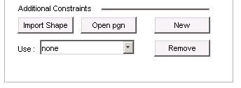
Constraints can be added to the Constraints Map by:
- Import Shape file (.shp) — can define several polygons.
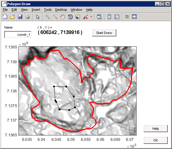
- Drawing constraints with the editor (press New); saved automatically to the Results Directory and reopened with Open pgn.